
Hacked ESP8266 RGB LED Controller
Tl;Dr: You can use these cheap Wifi RGB Modules from AliExpress/Ebay, and with a custom firmware they will speak MQTT and can be updated OTA as well as used for other features as desired. Download a copy of my custom firmware here, connect with the programming pads in the diagram here, configure Arduino to flash to a Generic ESP module with 1M flash (256Kbit SPIFFS) and bob’s your Uncle.
The remainder of this post will describe reverse engineering, writing and programming the custom firmware for this module. Follow along if your device uses an ESP8266 but differs slightly to my module.
As I was searching through my favourite online shop of cheap Chinese electronics, I came across this item for $5.50 + $2 shipping, which promises Wifi RGB LED control. The price suggests it could be using one of the cheap ESP8266 modules inside as its controller, so I went ahead and bought two. I have an addiction to ESP8266, LEDs and 18650 cells, so this could potentially fulfil two of my three afflictions.
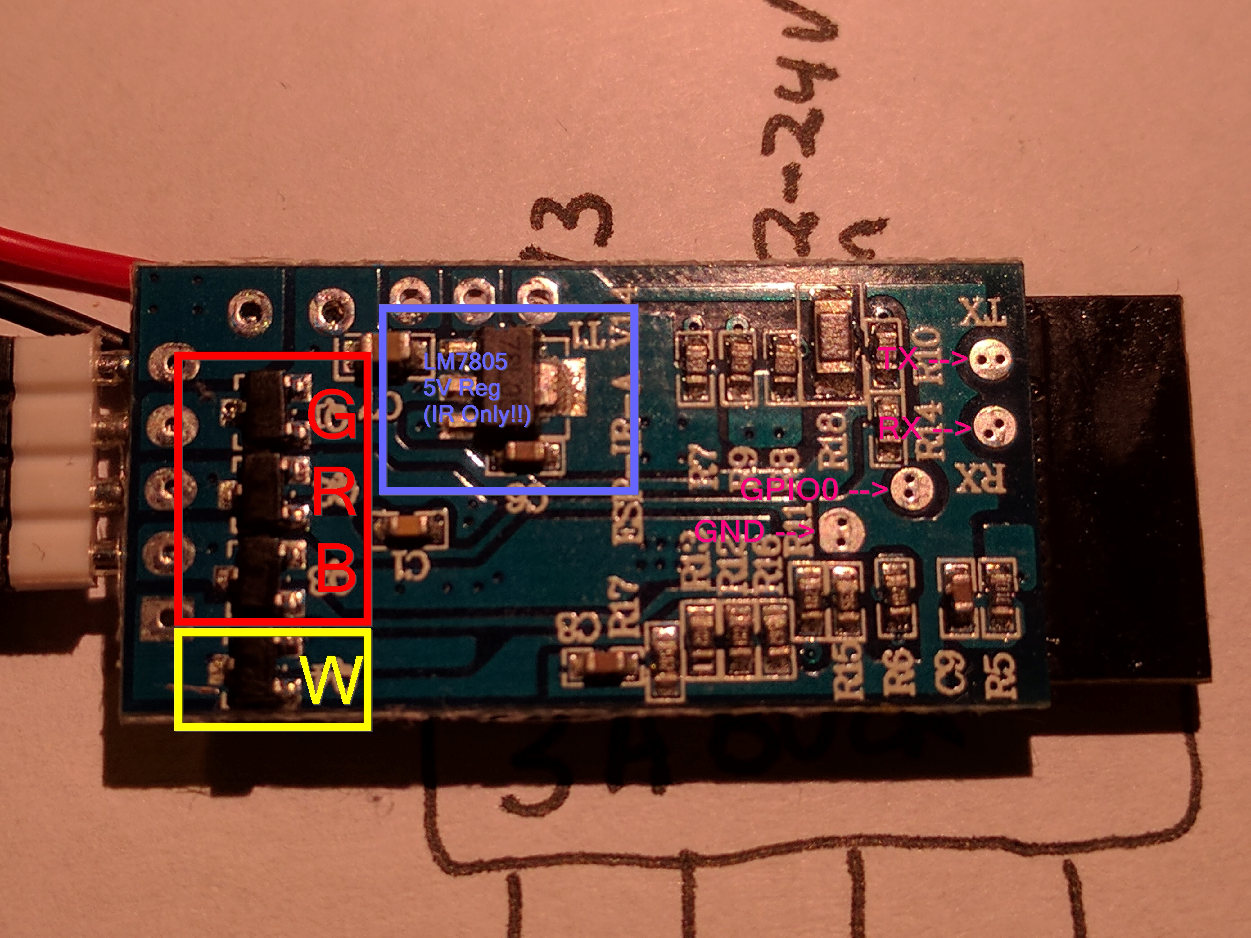
When it arrived, I immediately opened it up and was thrilled to see that it was based on an ESP-12S module, and additionally that my version had some extra unused components. It is not uncommon to have different versions of a board layout with certain components not populated; however, the manufacturer has made an error and populated unnecessary components to our benefit. Usually, if a device is destined to lack a feature such as an InfraRed Remote control, then all the components for the IR Receiver are left out. In this case, they have gone ahead and installed a LM7805 5V power supply, and a number of passive components to support the IR Receiver, but not the IR Receiver itself. This is great news, because not only does this convert 12-24v down to 3.3V for the ESP module, it also has an unused converter for 5V for any 5V accessories. Similarly, it is an RGB controller and has a four pin connector for RGB strips. Beside the fourth connector there is an unpopulated fifth socket — and behind this socket the MOSFET + all other supporting components for RGBW are populated. This means to convert the RGB-no-infrared model to RGBW with an Infrared remote, you’ll only need a fifth socket pin + IR Receiver module! Great news!
Below are pictures identifying the components.
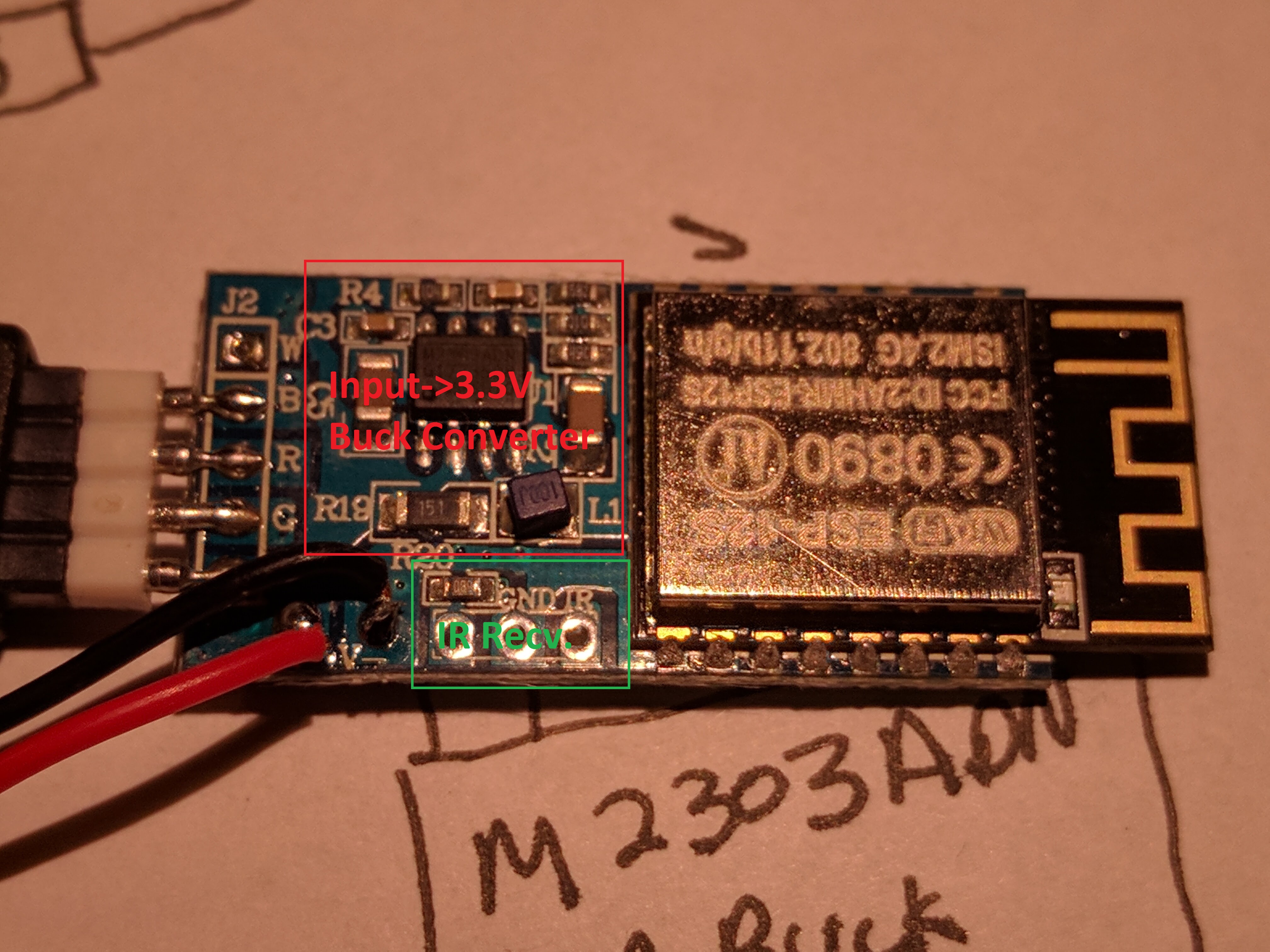
On to reverse engineering the pinouts. The first step was to use the continuity function of my multimeter to trace around to determine which pins of the ESP-12S module are connected to which outputs. I found the following table:
Infrared Input: 4
Red: 14
Green: 12
Blue: 5
White: 13
Unused*: 16
The schematic of the relevant connections (including pullups/pulldowns) is available here drawn with DaveCad 1.0
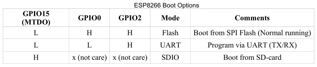
There are additionally four pads for programming on the underside of the board. These correspond to TX/RX (as marked), as well as GPIO0 and GND. To put the ESP8266 into programming mode, during startup, GPIO0 must be tied to ground. This is normally tied (via R8) to 3V3 enabling normal boot, but the programming pad allows us to change this to GND. In addition to GPIO0, GPIO2 and GPIO15 additionally play a special role in booting the ESP. These don’t change between booting in programming (UART) and normal (Flash) mode. If you’re considering using these pins, pay special attention to the table below as this may affect the booting:
If you’re planning on making a custom extension, such as a motion detector, it’s best to use the IR and unused* pin first.
With this in mind, the procedure to program firmware is then:
- Hookup TX/RX/GND/GPIO0 accordingly. I hand-hold wires onto the pads, which works most of the time.
- Setup the board information in Arduino (Generic ESP8266, 1M Flash, 256k SPIFFS, 80Mhz)
- Power up the module via the 12v LED plug
- Press program in the Arduino software
- Upon completion, release GPIO0 and unplug+plugin module to boot cleanly from the flash.
Code is available here
* I haven’t traced around the board to determine if this pin is in fact attached to anything; There is nothing on the board to suggest that it is but I haven’t verified this.